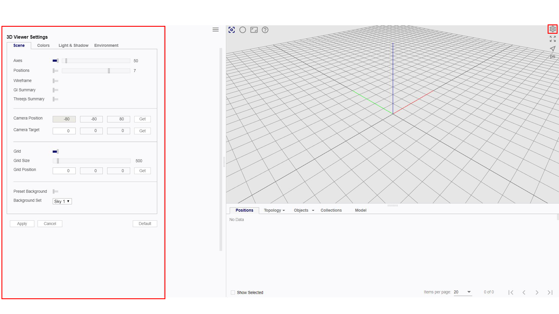
3D Viewer Settings
3D Viewer Settings can be accessed by clicking on the gear icon in the 3D Viewer. Users can alter various display settings in this section. They are categorised into 4 main groups namely Scene, Colors, Light and Shadows and Environment. In each of these categories, there are multiple settings that can be altered according to the user’s preference by changing the setting values or toggling the on/off switches.
Do note that the users have to save their alterations for them to be applied in the 3D Viewer.
Scene
Normals
When switched on, the normal of each polygon will be displayed. This is helpful in identifying whether the polygon is facing the intended direction.
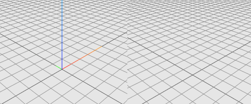
Axes
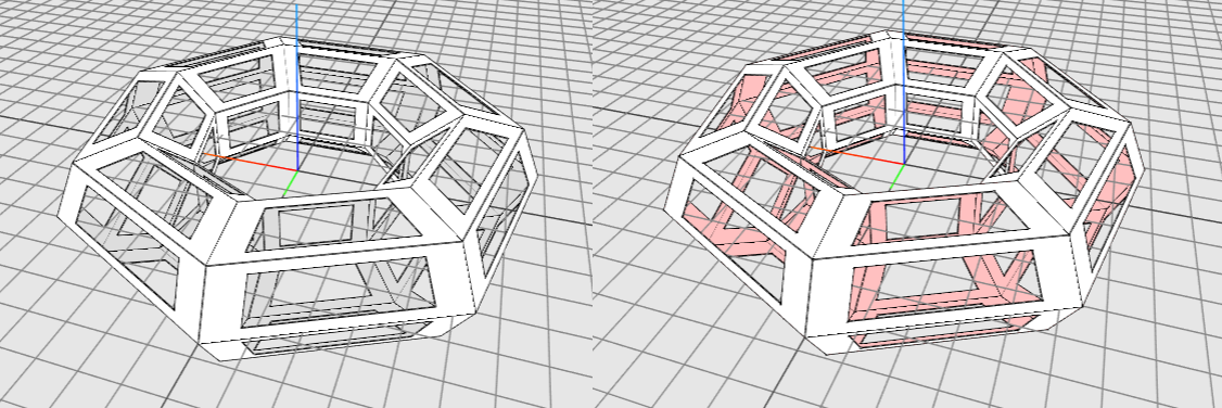
When switched on, the XYZ axes are displayed.
X axis: red
Y axis: green
Z axis: blue
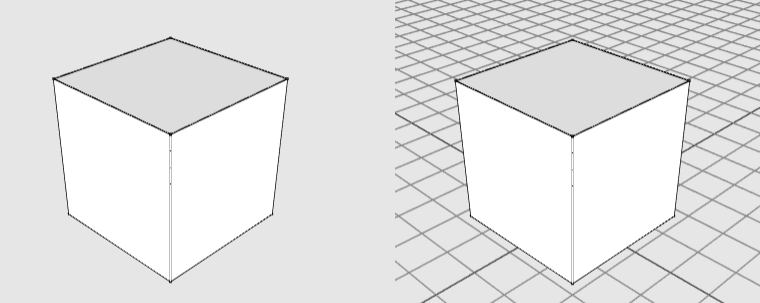
Grid
When switched on, a grid will be displayed on the XYZ plane with an origin of [0,0,0].
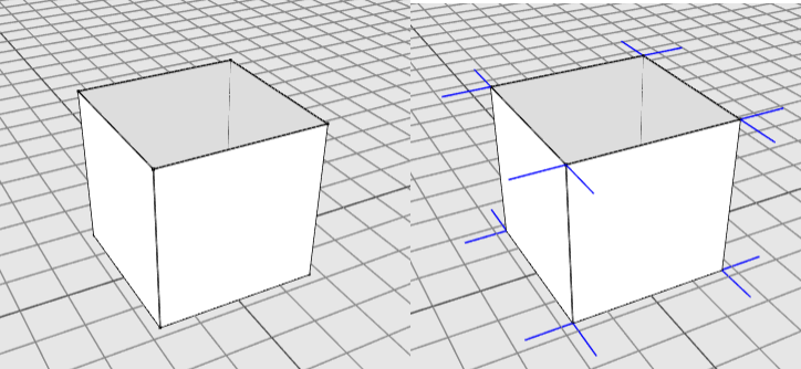
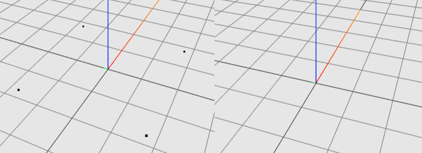
Positions
When switched on, each position will be represented as a black dot.
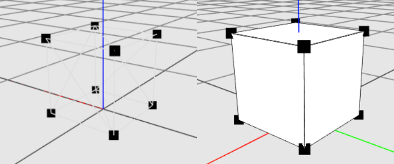
Wireframe
Wireframe mode allows users to see through the models.
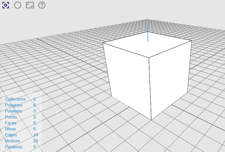
GI Summary
When GI summary is switched on, a summary table on the entities in the model is displayed on the bottom left corner of the 3D Viewer.
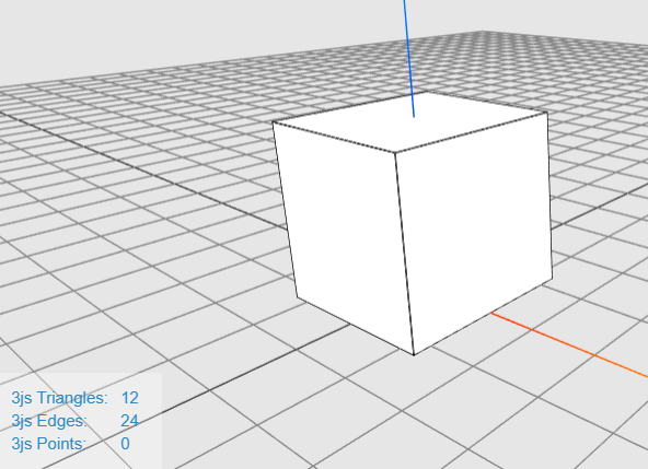
Threejs Summary
When switched on, a 3js information list on the rendered graphics of the model is displayed at the bottom left corner of the 3D viewer.
Camera
The camera feature is useful for users who wish to set the camera at a precise location or save certain viewing angles of the model.
Users can adjust the camera with more precision by keying coordinates into the three input boxes. Each of input boxes represent the X, Y and Z coordinates.
To save a specific viewing angle, simply click save and the model will be shown at that angle when loaded in the Mobius Modeller.
Colours
This section allows the user to change the colour of the 3D Viewer background and certain entities. One useful tip would be to change the colour of the “Face Back” item. This helps the user to identify back-facing polygons more easily.
Light and Shadow
Settings on Ambient Light, Hemisphere Light and Directional Light can be found in this tab. Users are free to experiment with the type of lights, change the light colour, intensity, shadows and other settings.
Environment
Settings on the Ground Plane can be found in this tab. A Ground Plane with customisable size, colour and shininess can be added into the 3D Viewer.