Transfer of Information between Nodes
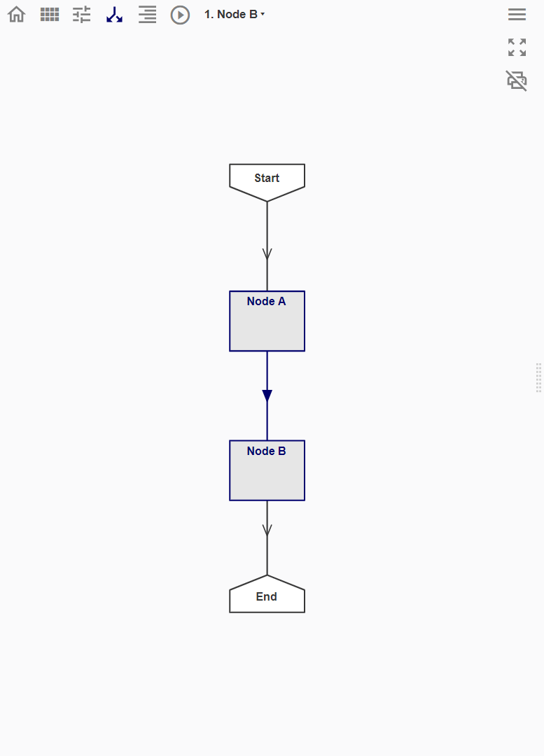
When Node B is created downstream of Node A, the Geo-info data model in Node A will be passed down to Node B. That means users can reference and work with the entities and attributes information from Node A using the query.Get function.
However, procedures from Node A are not transferred to Node B, as seen in the empty Procedure Space. Hence, the coding process in Node B start afresh. This means that variables created in the Node A can no longer be referenced, and users can have identical variable names in Node A and Node B without causing overwriting.
Distributed Workflow
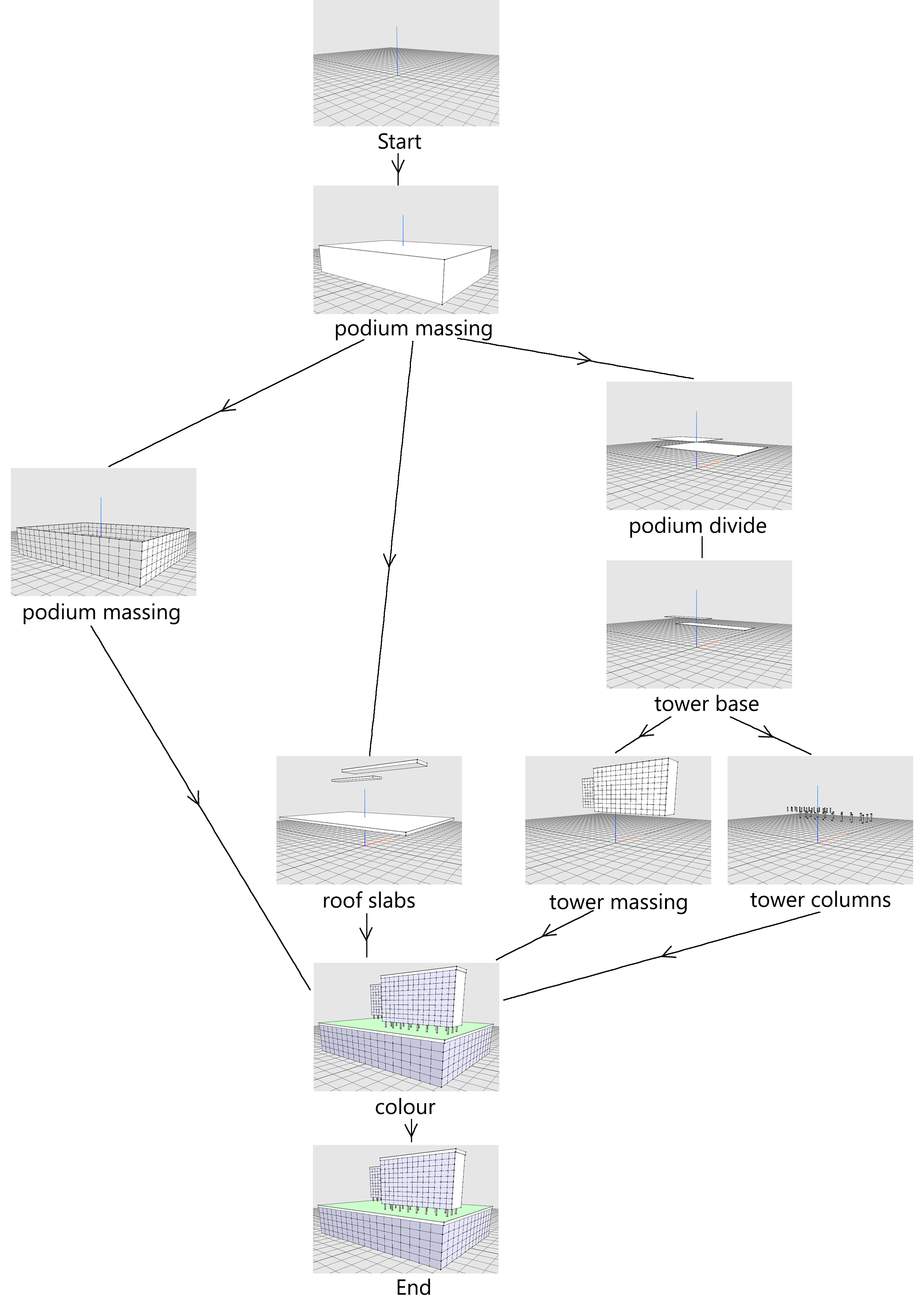
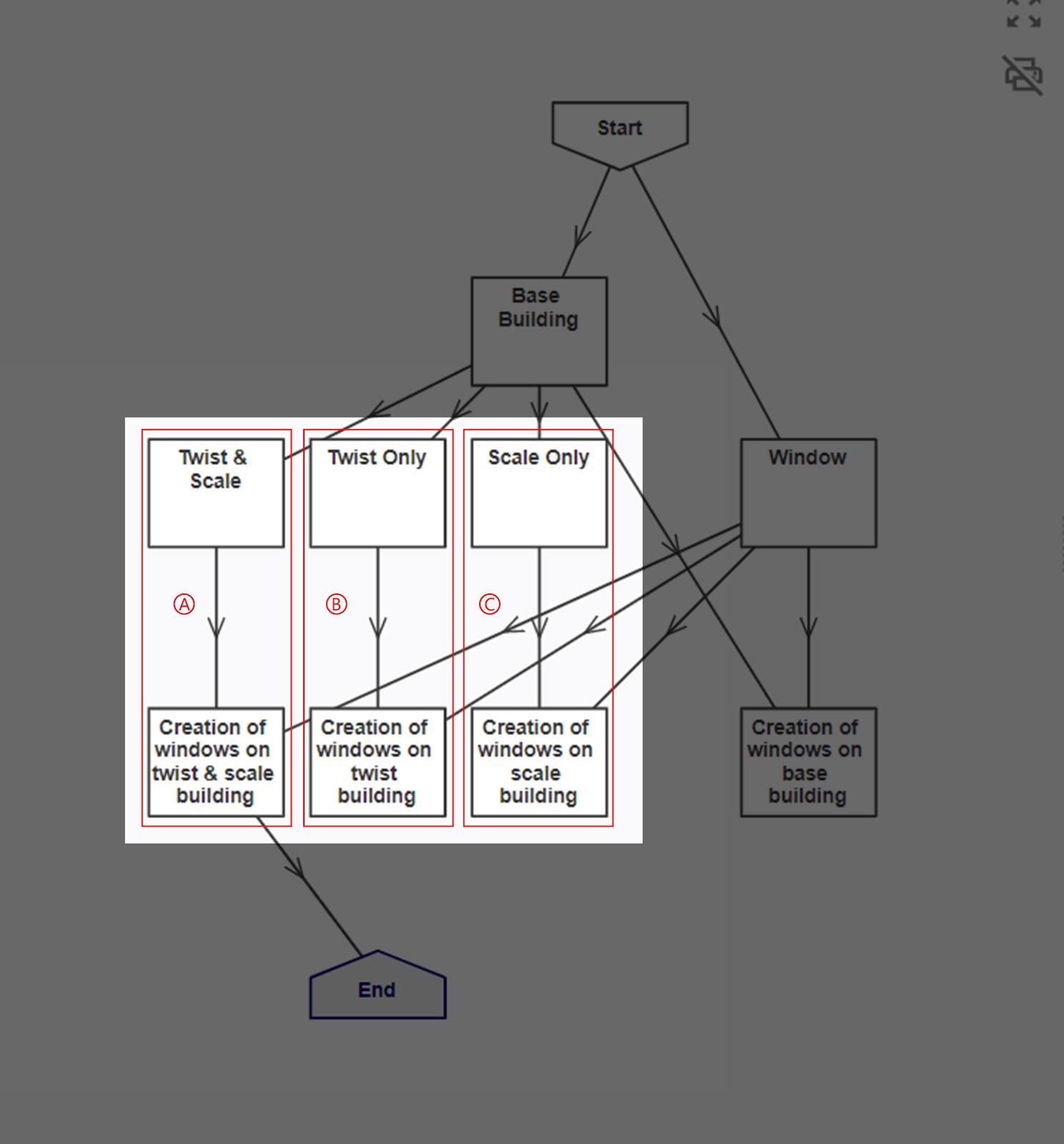
A distributed workflow refers to a decomposed modelling process that generates a flowchart made up of multiple nodes that code different components of a model separately. In Mobius, users are encouraged to take a distributed workflow approach to ensure the clarity of the flowchart and the modelling process.
A distributed workflow involves branching and merging. The first few nodes will branch out to create multiple instances of the base model, so that the subsequent nodes can reference the entity information from the base geometry using the query.Get function to code different components of the model.
The nodes making component eventually merge into one node to assemble the model. To prevent multiple copies of the base model in the final assembly, the base model is often deleted from each node it branches out using the function modify.Delete.
Nodes in Series
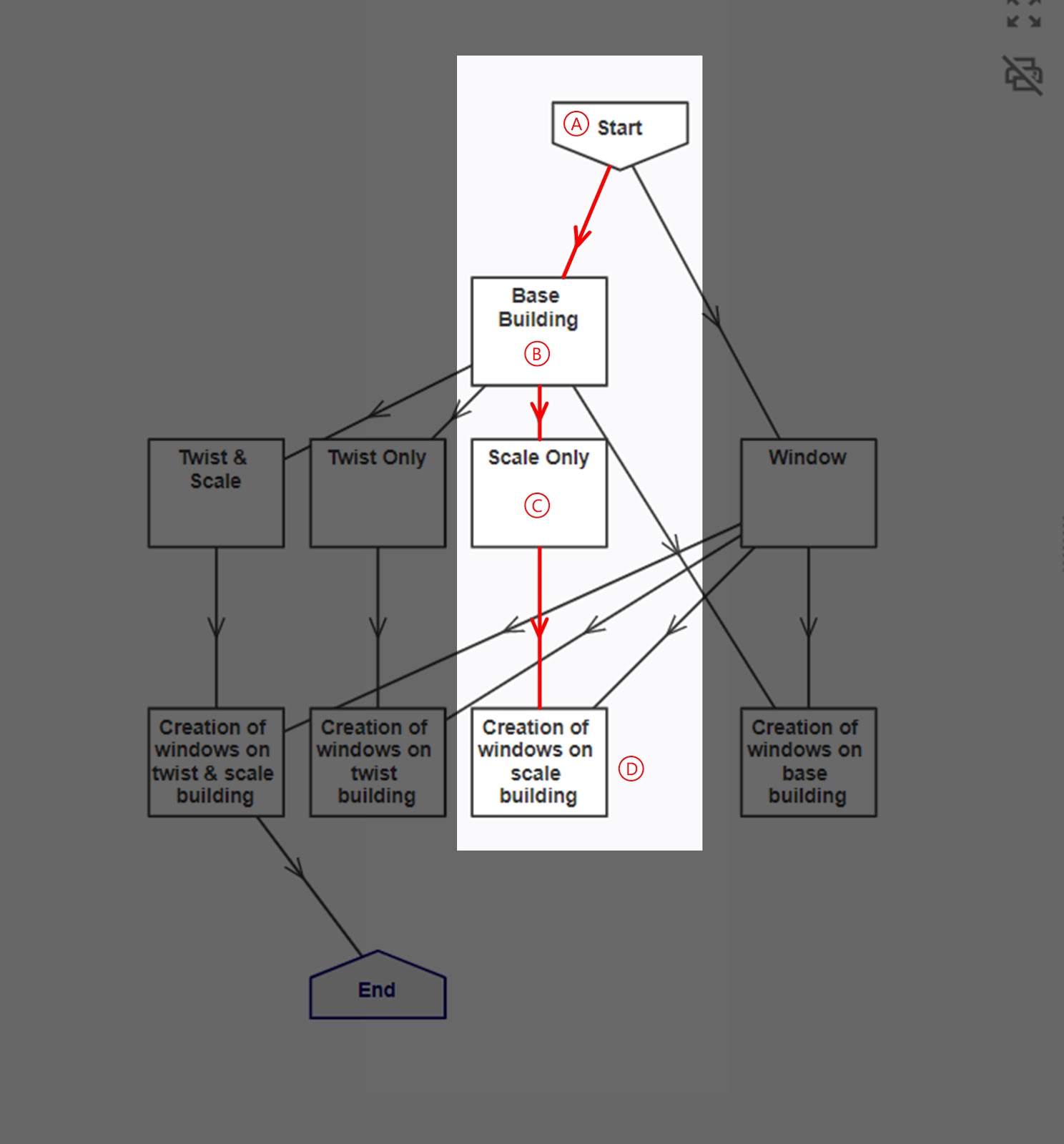
Nodes arranged in series refer to nodes that are linked together in one continuous sequence.
Nodes in Parallel
Nodes in parallel refer to nodes that are not directly linked to each other but are branched out from the same node upstream.
See Rules: Referencing Between Nodes, Hierarchy, Overwriting